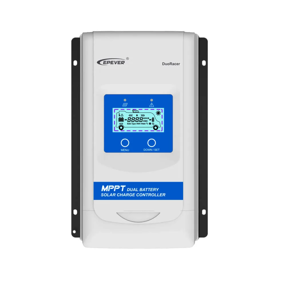
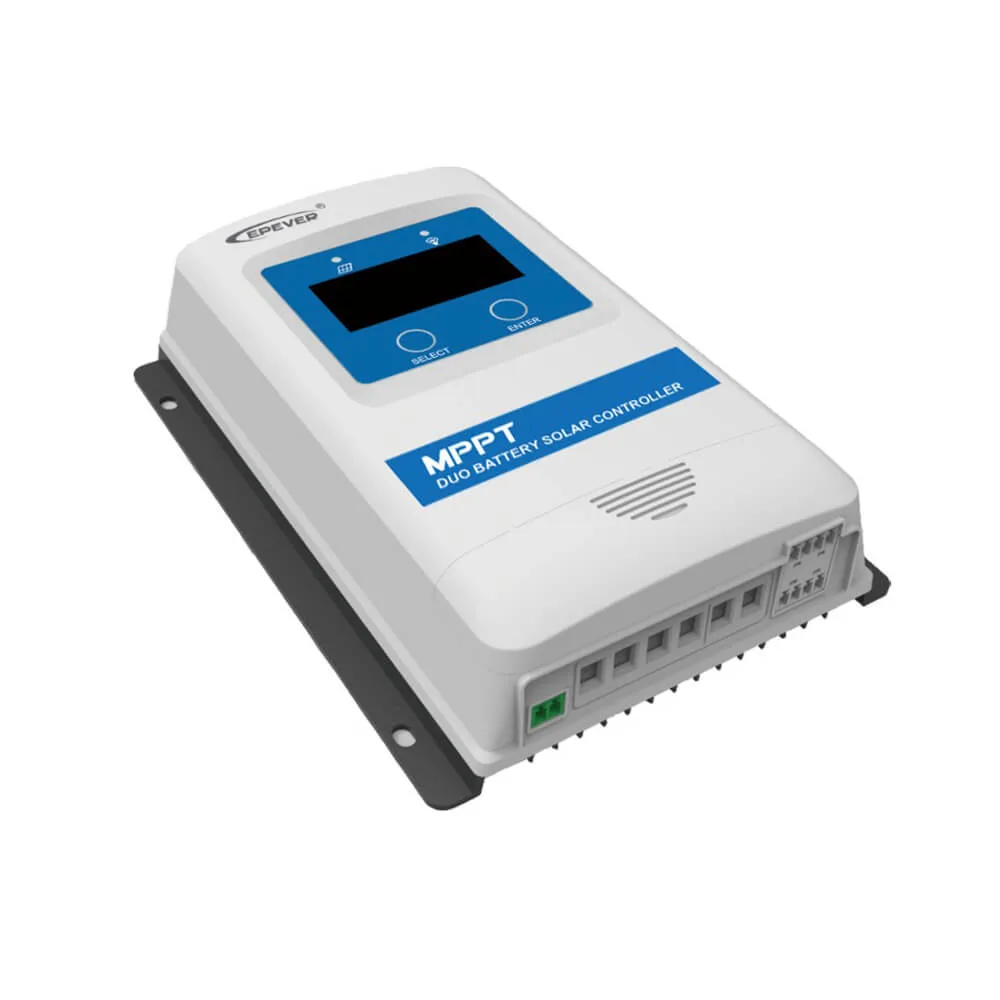
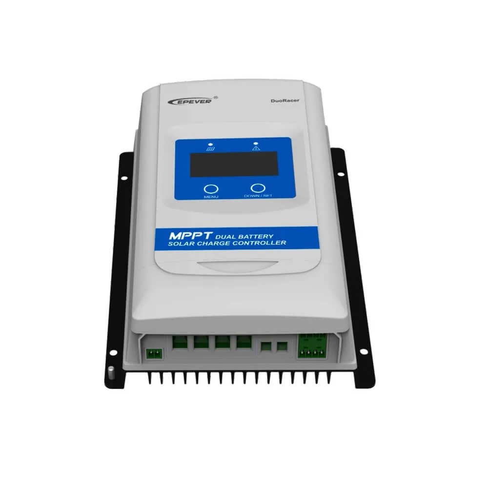
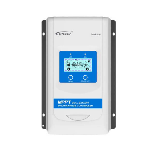

PowMr Epever 10A 20A 30A 12V/24V Dual Battery Charger Regulator DuoRacer 10A 20A 30A 12V/24V MPPT DuoRacer Solar Charge Controller For battery sealed, Gel, Flooded, LiFePO4, and Li-NiCoMn,which is suitable for RV, Camper, Boat
|
Voltage Optional:
|
|
|
Current Optional:
|
|


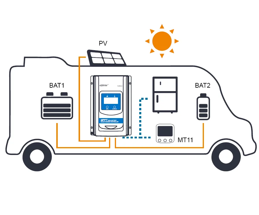
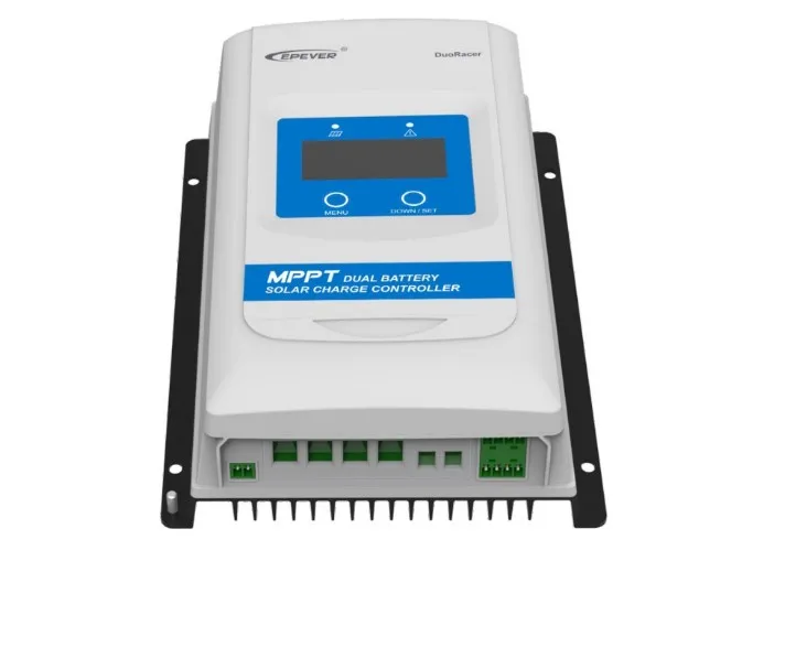
DuoRacer MPPT charge controller is made for charging two batteries (shown as BATT1 and BATT2 below) at the same time in a solar system. This controller supports multiple life battery (BATT1) types, including Sealed, Gel, Flooded, LiFePO4, and Li-NiCoMn, which is suitable for RV, Camper, Boat, and so on. The device recognizes the start battery (BATT2) system voltage automatically, and trickle charges the battery when the conditions are satisfied.
The controller adopts the advanced MPPT control algorithm,which will minimize the maximum power point loss rate and loss time,also fast track the maximum power point(MPP) of the PV array, and obtain the maximum energy from solar array under any conditions. The energy utilization in the MPPT solar system is increased by 20-30% compared with PWM charging method.
When there is no manual operation for a long time, and the charging conditions cannot be reached, the controller will turn to low-power mode, which reduces the loss and battery power waste to enhance the products life. The system parameters are shown and set by LED/LCD or the MT11 remote meter (Accessory).
The AES control signal of the car refrigerator is built in the controller, which will supply the surplus solar power to the refrigerator to avoid energy waste. The controller comes with IP33 protection level, which is waterproof and dustproof. Multiple protection features, including battery overcharge protection, over discharge protection, and reverse connection protection of the PV and battery, which effectively ensure the solar system safety, stability, and lifetime.
FEATURES:
Maximum Power Point Tracking technology with ultra-fast tracking speed and the tracking efficiency is no less than 99.5% guaranteed.
Advanced MPPT control algorithm to minimize the MPPlost rate and lost time
The wider range of the MPP operation voltage to improve the PV module utilization
Auto control function of charging power & charging current limitation(BATT1)
High quality and low failure rate components of ST, TI and Infineon to ensure the product life
Digital circuit control of adaptive three-stage charging mode to enhance BATT1 life.
BATT1 type can be set via LED/LCD.
Product runs into the low-power mode when there is no manual operation for a long time, and charging conditions are not satisfied (PV<5V).
100% charging and discharging in operationenvironmental temperature range.
LED and LCD dispiay units selectable.
AES control signal for car refrigerator to avoid energy waste.
Standard Modbus protocol, and RS485 (5V/200mA) communication port for the customer to expand the application area.
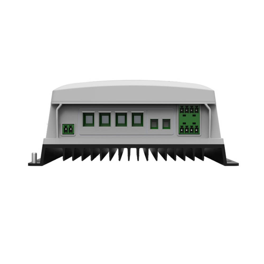
①Life battery (BATT1) is the energy storage battery for powering the household loads in the off-grid system, which supports Sealed, Gel,Flooded, LiFePO4, and Li-NiCoMn batteries (the controller can NOT recognize the system voltage automatically).
②Start battery (BATT2) is the energy storage battery which usually built in the vehicle for powering the system such as RV and Boat, and only supports lead-acid battery (the controller will recognize the system voltage automatically).
NOTE: the BATT1 and BATT2 must be at the same voltage level.
WARNING: When the power of PV is not greater than the rated charging
power, but the maximum open-circuit voltage of PV array is more than
60V(DR**06N-DDB/DDS)/100V(DR**10N-DDB/DDS)(at the lowest environmental
temperature), the controller may be damaged.
WARNING: When the power of PV is not greater than the rated charging
power, but the maximum open-circuit voltage of PV array is more than
60V(DR**06N-DDB/DDS)/100V(DR**10N-DDB/DDS)(at the lowest environmental
temperature), the controller may be damaged.
According to “Peak Sun Hours diagram”, if the power of PV array exceeds the rated
charging power of controller, then the charging time as per the rated power will be
prolonged, so that more energy can be obtained for charging the battery. However, in
the practical application, the maximum power of PV array shall be not greater than 1.5
times the rated charging power of controller. If the maximum power of PV array
exceeds the rated charging power of controller too much, it will not only cause the
waste of PV modules, but also increase the open-circuit voltage of PV array due to the
influence of environmental temperature, which may make the probability of damage to
the controller rise. Therefore, it is very important to configure the system reasonably.
For the recommended maximum power of PV array for this controller, please refer to
the table below:
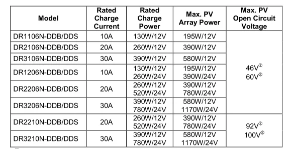
①At 25℃ environment temperature.
②At minimum operating environment temperature.
| Item | DR1206N-DDS | DR2210N-DDS | DR3210N-DDS |
| BATT1 rated voltage | 12/24VDC | ||
| BATT2 rated voltage | 12/24VDC Auto | ||
| Rated Charge Current | 10A | 20A | 30A |
| Battery Input Voltage Range | 8.5~32V | ||
| Max. PV Open Circuit Voltage | 60V | 100V | |
| Rated Charge Power | 130W/12V | 260W/12V | 390W/12V |
| 260W/24V | 520W/24V | 780W/24V | |
| Max. Conversion efficiency | 97.4% | 97.5% | 98% |
| Full load efficiency | 97% | 96% | 96% |
| Self-consumption | 12mA/12V;8mA/24V 4mA/12V;3mA/24V(Low-power mode) | 26mA/12V;15mA/24V 19mA/12V;10mA/24V (Low-power mode) | |
| Grounding | Common negative | ||
| BATT2Full voltage | 13.8V/12V;27.6V/24V(default) | ||
| BATT2 Charge return voltage | 13V/12V;26V/24V(default) | ||
| AES signal port | 5VDC/Max.200mA(2*(3.81-4P)) | ||
| RS485 com. port | |||
| Com. baud rate | 115200(default) | ||
| LCD backlight time | 60S(default) | ||
| Enclosure | IP33 | ||
| Dimension | 227.2×143×58.1mm | 243.7×158×63mm | 247.2×165×68.5mm |
| Mounting dimension | 160×134mm | 180×149mm | 180×156mm |
| Mounting hole size | 5mm | ||
| Terminal | 12AWG/4mm 2 (BATT1) | 6AWG/16mm 2 (BATT1) | 6AWG/16mm 2 (BATT1) |
| 12AWG/4mm 2 (BATT2) | 12AWG/4mm 2 (BATT2) | 12AWG/4mm 2 (BATT2) | |
| Recommended cable size | 12AWG/4mm 2 (BATT1) | 10AWG/6mm 2 (BATT1) | 8AWG/6mm 2 (BATT1) |
| 12AWG/4mm 2 (BATT2) | 12AWG/4mm 2 (BATT2) | 12AWG/4mm 2 (BATT2) | |